- August 30, 2024
Summarize with AI
Not enough time? Get the key points instantly.
Get summary:
Why Right Approach is Important to Build Vital Sign Monitor?
Your team has validated the concept. The clinical team wants heart rate, SpO2, and skin temperature. The product brief says 5 days on a single charge. It should sync to a companion app over BLE. The hardware engineer is asking which sensor to use. The firmware lead is asking how sensor data gets processed before it hits the radio.
Both are asking the right questions. Answer them wrong and you end up with a vital sign monitoring wearable that passes a bench test and fails on a human wrist every time. Motion artifacts corrupt the heart rate signal. The battery dies in 36 hours because the sensor runs continuously. The BLE connection drops during high-activity periods. None of these are bugs that show up in code review. They are architecture decisions made too early or too late.
By the end of this post, you will know how to design the sensor stack, firmware pipeline, and power architecture of a health wearable that behaves correctly on a real person, not just on a test bench.
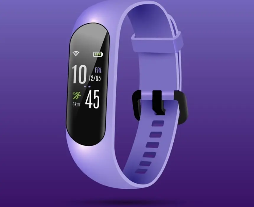
Why Vital Sign Monitoring Wearables Are Harder Than They Look
A heart rate monitor that works in a controlled lab is not the same product as a vital sign monitoring wearable that works during a 30-minute run, a night of restless sleep, or a clinical monitoring session where the numbers actually matter.
The gap between prototype and production almost always appears in three places.
Signal quality under real conditions. Optical heart rate sensors measure blood flow through changes in reflected light. Skin tone, ambient light, contact pressure, and body movement all affect that measurement. The same sensor that shows a clean signal on a desk produces a noisy, artifact-filled reading on a moving wrist. Turning that noisy signal into a usable heart rate number requires real signal processing. Reading the raw sensor output is not enough.
Continuous power draw. Sensors that sample continuously draw current continuously. A firmware design that never sleeps the sensor pulls too much current. A typical wearable battery drains in under two days. A working design turns the sensor on for short bursts, processes the data, and sleeps everything between cycles.
Multiple sensors working together. Heart rate from an optical sensor alone is unreliable during movement. That is a firmware problem, not a hardware one. Accurate heart rate during activity requires combining the optical signal with motion data to separate real pulse readings from movement noise. That combination runs on the processor and adds complexity that competes with everything else the device is doing.
Get these three right in the design phase and the firmware team has a clean foundation. Miss one and the first user test exposes it.
Pick Your Sensor Stack Before the Hardware Design Starts
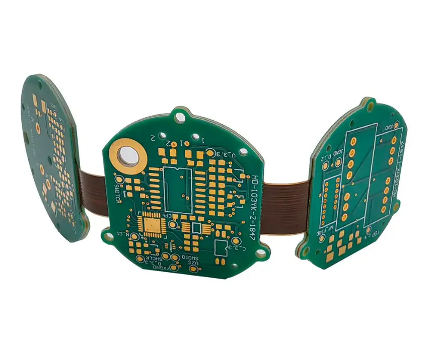
The sensors you choose determine everything downstream: power budget, signal processing complexity, processor requirements, and how the PCB needs to be laid out. Lock the sensor selection first. No schematic work should start before this.
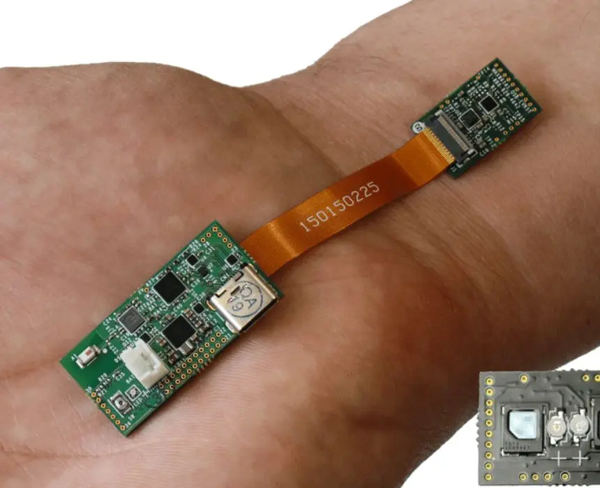
Optical sensor for heart rate and SpO2
An optical heart rate sensor works by shining light into the skin and measuring how much bounces back. As blood pulses through the capillaries, the reflected light changes slightly. That variation is the signal the sensor captures. SpO2 adds a second light colour and compares how each is absorbed to estimate blood oxygen level.
Two sensors appear most often in production health wearables. The MAX30102 is the more common choice for consumer and clinical devices because it handles both heart rate and SpO2, integrates cleanly with most microcontrollers, and keeps the component count low. The AFE4404 suits more demanding clinical applications. The AFE4404 is preferred when signal quality is the priority over cost , it has a lower noise floor and suits more demanding clinical applications.
Both sensors handle the light emission, detection, and signal conditioning internally. The processor receives clean digital readings rather than raw analog signals, which simplifies the firmware and reduces the risk of noise problems from PCB layout.
Sensor placement on the PCB matters as much as which sensor you pick. The light source and detector need consistent contact with the skin, consistent pressure, and protection from ambient light leaking in from the sides. This is a hardware design challenge that needs to be solved during PCB layout, not after the first prototype comes back.
Motion sensor for accuracy during activity
Every production heart rate wearable that claims accuracy during exercise includes a motion sensor. Its job is to tell the firmware which readings from the optical sensor were corrupted by movement, so those samples can be excluded or corrected before calculating heart rate.
The motion sensor needs to sample at the same rate as the optical sensor. It should also include onboard memory to buffer readings between processor wake cycles. This buffering means the processor does not need to stay awake continuously just to collect motion data , it can sleep and collect the buffered data in one batch.
Temperature sensor
Skin temperature adds a third vital sign for minimal additional cost. A temperature sensor accurate to within a fraction of a degree is straightforward to integrate and draws almost no current in standby. Temperature does not need frequent readings , once every 30 seconds is more than sufficient for most monitoring applications.
Vital Sign | Sensor | Sample frequency needed | Power impact |
|---|---|---|---|
Heart rate + SpO2 | Optical | High (25–100 readings/sec) | Highest — LED is main draw |
Motion (for accuracy) | Accelerometer | Medium (25–50 readings/sec) | Medium |
Skin temperature | Digital temperature sensor | Very low (1 per 30 sec) | Negligible |
Choose the Processor Based on Connectivity and Battery Life Target
The processor determines which wireless stack is available, how deeply the device can sleep between sensor readings, and how much signal processing headroom exists. For a vital sign monitoring wearable, the choice almost always comes down to two options.
For BLE-only devices with long battery life targets
The nRF52840 from Nordic Semiconductor is the most common processor in production health wearables. It integrates BLE 5.0, has enough processing power for heart rate and SpO2 algorithms, and reaches very low sleep current when the processor is idle between sensor cycles: around 3 microamps. Nordic also provides a power measurement tool that connects to the development board and shows real current consumption with microsecond resolution. Being able to see exactly what the hardware draws during each phase of the duty cycle before finalising the design is a significant development advantage.
For a wearable targeting 5-day battery life with BLE-only connectivity, this processor is the right starting point because the SDK is mature, the BLE stack is well-tested in production, and the power tooling makes optimisation measurable rather than estimated.
For devices that need Wi-Fi or on-device AI
The ESP32-S3 makes sense when the wearable needs Wi-Fi in addition to BLE, or when on-device signal processing at a level beyond standard heart rate algorithms is required. It has significantly more processing power but draws more current in sleep mode. For devices where battery life is the primary constraint and BLE connectivity is sufficient, the nRF52840 remains the better fit.
Processor | Wireless | Sleep Current | Best Fit |
|---|---|---|---|
nRF52840 | BLE 5.0 | Very low (~3µA) | BLE-only wearables, long battery life |
ESP32-S3 | BLE 5.0 + Wi-Fi | Low (~7µA) | Wi-Fi needed, or on-device AI |
Design the Firmware Around Sensor Duty Cycling
The firmware architecture of a vital sign monitoring wearable has one constraint above all others: the optical sensor consumes more power than everything else when running. The firmware must minimise the time it is active without losing signal quality.
How duty cycling works in practice
Running the optical sensor continuously for heart rate monitoring uses enough power to drain a typical wearable battery in one to two days. The solution is to run the sensor in short bursts. The sensor wakes. It collects readings for a few seconds. The processor calculates heart rate. Then both go back to sleep.
For a resting heart rate monitor, this cycle runs roughly once per minute. For an activity monitor, the cycle runs more frequently because the user needs faster updates. The accelerometer detects movement. It triggers the processor to shorten the sleep interval automatically.
This duty cycling approach reduces the sensor's average power draw by 80 to 90% compared to continuous operation. That is the difference between a 36-hour device and a 5-day device, on the same battery and the same hardware.
How the firmware tasks are organised
A health wearable runs several things simultaneously: reading sensors, processing the signal, managing the BLE connection, and monitoring the battery. Organising these as separate software tasks (each with its own responsibilities and priority) keeps the design clean and makes debugging significantly easier than a single-loop firmware approach.
The sensor reading task wakes at the duty cycle interval, collects data, and passes it to the processing task. The processing task converts raw readings into heart rate and SpO2 values and makes them available for transmission. The BLE task sends notifications to the phone when a new result is ready. A separate system task monitors battery level and handles any fault conditions.
The connection between tasks needs to be sized correctly. If the processing task falls behind the sensor task, readings are lost. Dropped readings during a computation window corrupt the heart rate output. Sizing the data buffer between tasks to hold at least one full computation window prevents this.
Motion artifact handling
Heart rate accuracy during movement is where most consumer wearables fall short. The optical signal during walking or running contains both the real pulse and the noise from arm movement. Without motion compensation, the heart rate algorithm locks onto the noise frequency instead of the pulse frequency.
The accelerometer output runs at the same time as the optical sensor during activity. The firmware uses it to identify which optical readings were corrupted by movement and exclude them from the heart rate calculation. A more sophisticated approach subtracts the motion component from the optical signal rather than just rejecting affected samples.
On one health wearable development project, the initial heart rate reading without motion compensation showed an average error of 18 beats per minute during moderate walking. After adding motion-based correction to the firmware, average error dropped to 4 beats per minute on the same hardware with no hardware change.
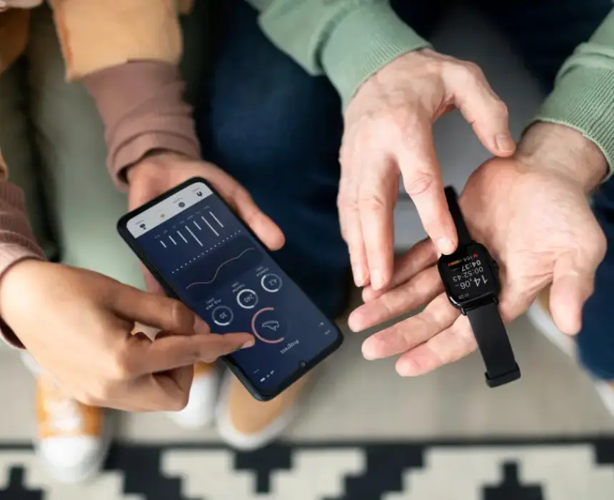
Build the BLE Architecture Before Writing Any Firmware
The wireless design of a vital sign monitoring wearable affects battery life, user experience, and how well the companion app works in real conditions. These decisions need to happen before firmware development starts, not during it.
What data to send and how often
BLE sends data at a connection interval: a fixed time window where the device and phone exchange packets. A short connection interval means more frequent radio activity, which drains the battery faster. For a device producing a new heart rate reading once per second, a connection interval of 1 to 2 seconds makes sense. Sending data more frequently than readings are produced wastes radio energy without any benefit to the user.
Standard Bluetooth health profiles exist for heart rate and pulse oximetry. Using them means standard health apps on iOS and Android can read the device's data without a custom integration. Custom profiles make sense when the data format is proprietary or when the companion app handles all data display and storage.
Handling disconnection
BLE connections drop regularly. The phone screen locks, the user walks out of range, or another app claims the radio. A wearable that stores readings locally when disconnected and uploads the backlog when the connection re-establishes is a significantly better product than one that discards data during gaps.
The firmware needs: local storage for readings collected during disconnection, a state machine that tracks connection status without corrupting the current measurement session, and a sync process that transfers stored readings efficiently when the connection returns. Designing this before writing any BLE code prevents the most common reconnection problem. When the connection drops, the device should continue the existing session, not start a new one.
Calculate the Power Budget Before Selecting the Battery
Most teams select a battery based on how much space the enclosure allows, then hope it lasts long enough. The right approach is the reverse: calculate the average power draw from the sensor duty cycle design, derive the battery capacity needed, and then constrain the enclosure around that number.
How to estimate average current draw
Each component has two states: active and asleep. Each state has a known current draw. The duty cycle, the fraction of time spent in each state, determines the average contribution of that component to the overall power budget.
For a vital sign monitoring wearable with the sensor duty cycle described in this post, total average current typically falls between 1 and 2 milliamps. A 200mAh battery at 1.5mA average draw lasts approximately 133 hours. That is just over 5 days. The brief is met. That meets the brief. A 150mAh battery at the same draw lasts 100 hours , borderline. Knowing this before PCB layout is the point.
Battery chemistry and charging
Lithium polymer cells are standard for wrist-worn health wearables. They are thin, flexible in shape, and available in the 150 to 300mAh range that suits wearable form factors. Charging is handled by a dedicated charging IC that manages the charge cycle safely and protects the cell from overcharge.
The firmware also needs a low-battery shutdown. When the battery drops below a safe threshold, the device should save any pending data, close the BLE connection cleanly, and power down. Letting the processor run as voltage drops produces unpredictable behaviour.
Frequently Asked Questions
What sensors does a vital sign monitoring wearable need?
The core sensor stack for heart rate and SpO2 combines an optical sensor (measures blood flow through reflected light) with a motion sensor to improve accuracy during activity. Adding a skin temperature sensor brings in a third vital sign at minimal additional cost and power draw. For clinical monitoring applications, an ECG electrode can be added to capture electrical heart activity rather than optical , but this requires a different sensor type and significantly more firmware complexity.
How long should a vital sign monitoring wearable battery last and how do you achieve it?
A 5 to 7 day battery life is achievable with a 200mAh lithium polymer battery, provided the sensor duty cycle is designed correctly. The key is not running the optical sensor continuously , instead, sampling in short bursts every 30 to 60 seconds for resting mode and more frequently during detected activity. The BLE connection interval also needs to match the actual data rate. Combining sensor duty cycling with a connection interval of 1 to 2 seconds typically brings average system current to 1 to 2 milliamps, which supports multi-day operation on a battery that fits inside a wrist wearable.
How does a wearable measure heart rate accurately during exercise?
Optical heart rate sensors produce a noisy signal during movement because arm motion affects the reflected light in the same way blood pulses do. Accurate heart rate during exercise requires the firmware to run the optical sensor and a motion sensor simultaneously, and use the motion data to identify and remove readings that were corrupted by movement before calculating heart rate. Without this step, the heart rate algorithm often locks onto the movement frequency rather than the actual pulse, producing readings that are significantly wrong during activity.
What is the difference between a consumer heart rate wearable and a clinical vital sign monitoring wearable from a hardware and firmware perspective?
Consumer wearables optimise for battery life and comfort, often at the cost of measurement accuracy. Clinical wearables need tighter accuracy tolerances. That means higher-quality sensors, more careful hardware layout, more sophisticated signal processing, and continuous monitoring rather than periodic spot checks. The firmware architecture for a clinical wearable also needs to handle data integrity more carefully , including secure local storage, synchronisation logging, and alert thresholds that trigger regardless of BLE connection status.
How do you handle BLE disconnection on a health wearable?
The firmware needs to detect disconnection, switch to local storage mode, continue collecting and storing readings, and synchronise the backlog when the connection re-establishes. This requires: a ring buffer in local storage sized for the expected maximum disconnection duration, a state machine that tracks session continuity across disconnection events, and a sync protocol that prioritises older readings first to maintain chronological data integrity. Wearables that simply discard data during disconnection produce gaps in the monitoring record that are unacceptable in any clinical or research use case.
How accurate is SpO2 on a wrist-worn wearable?
Wrist-based SpO2 using the optical method is less accurate than fingertip pulse oximetry because wrist blood flow is lower and more affected by motion and skin tone. Consumer wearables typically achieve ±2 to 3% SpO2 accuracy under ideal conditions. Accuracy degrades significantly during movement or poor sensor contact. The primary factors that affect SpO2 accuracy are LED wavelength calibration, sensor placement geometry, and the algorithm used to convert the optical ratio to a percentage. For spot-check monitoring, wrist SpO2 is clinically useful. For continuous monitoring where accuracy is critical, fingertip or earlobe sensor placement produces more reliable results.
Conclusion
Building a health monitoring wearable that works on a real person rather than a test bench comes down to three decisions made early: which sensors go into the stack and how they are placed on the PCB, how the firmware duty-cycles those sensors to meet the battery life target, and how the BLE architecture handles data flow and disconnection before a line of firmware is written.
Get those three right before the schematic is locked and the development path is straightforward. Discover them during user testing and each one is a hardware revision or a firmware rewrite.
If you are scoping a vital sign monitoring wearable and want a team that handles sensor hardware, firmware signal processing, and the companion app without handoff gaps, CoreFragment's hardware and firmware team has built health monitoring devices across consumer, clinical, and research use cases. Share your requirements and you will get a direct assessment of what your sensor stack, firmware architecture, and battery strategy should look like.
Author
Have Something on Your Mind? Contact Us : info@corefragment.com or +91 79 4007 1108
Related articles

_title.webp)