- October 05, 2026
Summarize with AI
Not enough time? Get the key points instantly.
Get summary:
Why Fleet Tracking Technology Selection is Important?
Your pilot fleet of 20 vehicles looks perfect on the demo map. Then a truck enters a tunnel, the tracker loses its cellular link, and 40 minutes of route history vanish. Scale that to 500 vehicles and dispatchers stop trusting the dashboard.
Wrong early choices on the modem, the firmware buffering, or the message protocol turn into hardware respins after installation. You cannot patch a tracker bolted under a dashboard in a truck 400 km away.
Here is how to develop a GPS fleet tracking system that holds up in the field. By the end, you can pick your hardware, define the firmware behavior, choose your protocols, and size the cloud backend before you commit budget.
Why Fleet Trackers Fail After the Pilot Phase
Most failures trace back to one wrong assumption: that a vehicle behaves like a desk. Vehicles drive through tunnels, park in concrete garages, and cross rural dead zones. Their power drops during engine crank. They sit idle for weeks and drain any backup battery.
A GPS fleet tracking system has four jobs, and each one breaks in its own way:
Position accuracy: buildings reflect GNSS (satellite navigation) signals and cause multipath errors, so a fix in a dense city can drift by tens of meters.
Data delivery: cellular coverage has gaps, so any design that sends each point instantly loses data.
Power: a tracker that wakes the modem every few seconds drains a parked vehicle's battery in days.
Scale: 1,000 vehicles reporting every 10 seconds generate 8.64 million messages a day.
Naming these failure modes first matters because each one maps to a design decision in GPS fleet tracking system development. Fleet buyers also judge reliability before features. A tracker that reports every 30 seconds and never loses a trip beats one that reports every 5 seconds and drops one in twenty.
Map the Four Layers of a GPS Fleet Tracking System Before You Write Code
Every GPS fleet tracking system architecture has four layers. The table shows what each layer does and the first decision you must lock.
Layer | What it does | First decision to lock |
|---|---|---|
Hardware | Holds the GNSS receiver, modem, and power stage | Plug-in OBD-II unit or hardwired unit |
Firmware | Buffers data, schedules reports, and updates itself | RTOS and flash layout |
Protocols | Define how each hop talks: vehicle, GNSS, modem, cloud | Payload format and transport (MQTT, HTTPS, or UDP) |
Cloud | Ingests, deduplicates, stores, and runs geofence rules | Broker and time-series database |
Lock the hardware layer of your GPS fleet tracking system first. Once units sit in vehicles, hardware changes mean truck rolls, while cloud code can change every week. Firmware comes second because it must fit the memory and power limits the hardware sets.
Choose GPS Tracker Hardware: GNSS, Modem and Power
GPS tracker hardware design comes down to three parts: the satellite receiver, the cellular modem, and the power stage.
Pick a multi-constellation GNSS receiver (GPS, Galileo, GLONASS, BeiDou) because more visible satellites improve fixes between buildings. Open-sky accuracy sits around 2 to 3 meters for modern modules from u-blox and Quectel. Place the antenna with a clear view of the sky, and test on the actual windshield glass your fleet uses, because coated glass can block signals. Modem choice carries more risk than receiver choice:
Connectivity | Mobility support | Best for | Trade-off |
|---|---|---|---|
LTE-M | Handles cell handover at vehicle speed | Cars, vans, and trucks sending small payloads | Coverage and roaming vary by carrier and country |
LTE Cat 1 | Full mobility, higher throughput | Dashcam data, large firmware images | More power draw and higher module cost |
NB-IoT | Built for stationary devices | Parked trailers and containers | Limited mobility support and higher latency |
2G fallback | Networks are shutting down in many regions | Legacy regions only | Hardware shipped today can outlive the network |
For a first product, LTE-M is the right starting point because it balances power, cost, and mobility. Switch to a single Cat 1 design if your target countries lack LTE-M roaming agreements.
Power needs the same care. Passenger cars run 12 V and trucks run 24 V, and both produce voltage spikes at engine crank. A wide-input regulator (9 to 36 V) survives both. A small backup cell lets the unit send a final "power cut" message, which is your best tamper alert. Standby current decides how long the backup cell lasts, so apply the embedded power optimization techniques from the first schematic.
You must also choose the install style. Telematics device development usually splits into two paths:
Plug-in OBD-II unit: installs in under a minute and reads engine data from the CAN bus (the vehicle's internal network), but a driver can unplug it.
Hardwired unit: resists tampering and can read ignition state or drive a relay, but needs a trained installer.
How to Write Firmware for GPS Tracking Device
In a GPS fleet tracking system, firmware decides whether the data arrives. Run it on an RTOS such as Zephyr or FreeRTOS, because you must handle GNSS parsing, modem state, CAN reads, and flash writes at the same time. Five rules separate field-ready firmware from demo firmware:
Buffer first, send second. Write every fix to a flash ring buffer and upload in batches. A tunnel then costs you delay, not data.
Report on events, not only timers. Send a point when heading changes by 15 degrees, distance passes 200 meters, or ignition flips. These example thresholds cut data volume compared with fixed 5-second pings.
Sleep on motion. Wake from an accelerometer interrupt so a parked unit sleeps instead of holding the modem awake.
Guard the modem. A watchdog timer resets the unit when the modem hangs on an AT command (the text commands that control it). Without one, a single stuck command silences the tracker until someone visits it.
Plan updates from day one. An over-the-air (OTA) update lets you push new firmware through the cellular link. Use a dual-bank layout so a failed update rolls back instead of bricking the unit. Our guide on why OTA updates matter for IoT devices covers the mechanics.
Choose the Right Protocol at Every Hop
A GPS fleet tracking system runs four separate conversations, and each one uses its own protocol:
Vehicle to device: OBD-II requests (PIDs) for cars and SAE J1939 messages for heavy trucks, both carried over the CAN bus.
GNSS receiver to microcontroller: NMEA 0183 text sentences or u-blox's binary UBX messages over UART. UBX is the better pick because binary parsing costs less CPU and one message carries position, speed, and accuracy estimates.
Microcontroller to modem: AT commands over UART on most cellular modules.
Device to cloud: the transport choice in the table below.
Transport shapes your data bill and your server design:
Protocol | Overhead | Fits when | Watch out for |
|---|---|---|---|
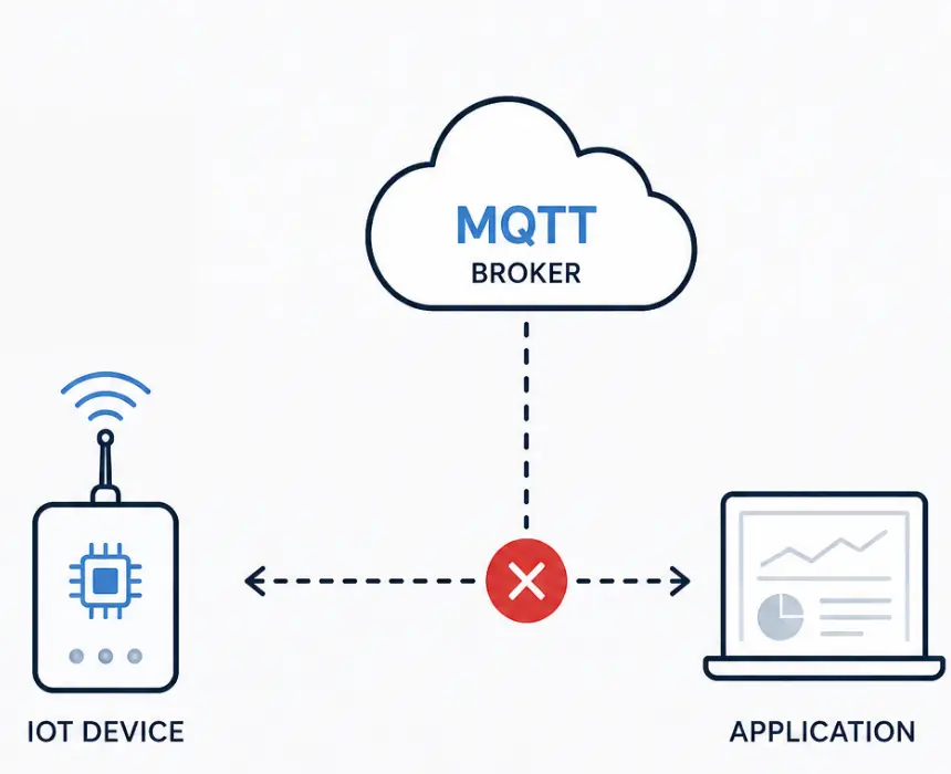
MQTT over TLS | Low, with a persistent connection | Most fleets, and any design that sends commands to devices | Broker scaling and keepalive tuning on cellular networks |
HTTPS POST | Higher, one request per batch | Simple batch uploads from sleeping devices | Header overhead adds data cost across a large fleet |
Raw UDP or TCP, binary payload | Lowest | Very large fleets where data cost dominates | You build framing, retries, and security yourself |
For a deeper comparison, read our breakdown of MQTT vs HTTP for device messaging.
Encode payloads in binary with Protobuf or CBOR, because a position message shrinks from roughly 150 to 200 bytes in JSON to about 30 to 40 bytes [verify before publishing]. On a 1,000-vehicle fleet, that gap decides your cellular bill. Use MQTT QoS 1 (at-least-once delivery) for positions because your cloud already deduplicates, and match the keepalive interval to your carrier's idle timeout. Wrap every connection in TLS, or DTLS if you choose UDP.
Design the Cloud Backend for Constant Position Streams
Inside a GPS fleet tracking system, the tracker's job ends at the cellular link. Your cloud must authenticate each device, ingest every message, remove duplicates, and answer map queries fast. Deduplicate on device ID plus timestamp, because store-and-forward firmware replays old points after a dead zone.
Stage | Options | Watch out for |
|---|---|---|
Broker | EMQX, Mosquitto, AWS IoT Core | Per-device certificates and connection limits during mass reconnects |
Queue | Kafka or a managed queue | Partition by device ID to preserve point order |
Workers | Validate, deduplicate, apply geofences | Late and out-of-order points after dead zones |
Storage | TimescaleDB with PostGIS for spatial queries | Retention: keep raw points short term and downsample the rest |
Each stage scales on its own, so a burst of reconnecting vehicles after a network outage does not crash your database. Add a downlink channel on the same broker so you can push configuration changes, such as a new report interval, without a firmware release. Dashboards and driver apps then read from the API in front of this store.
Start with the Device, Then Scale the Platform
Start with the device and its protocols. If the tracker buffers data, sleeps correctly, and updates safely, your cloud team can iterate for years. If it fails those tests, no dashboard fixes it. GPS fleet tracking system development rewards teams that settle the hardware and message format early, because both are the hardest things to change after installation.
If you are scoping a GPS fleet tracking system and want a team that handles hardware, firmware, protocols, and cloud without handoff gaps, CoreFragment's embedded software development team can review your requirements and give you a direct recommendation on modem, GNSS module, and message design, with a realistic timeline.
Author
Have Something on Your Mind? Contact Us : info@corefragment.com or +91 79 4007 1108

Related articles
_title.webp)